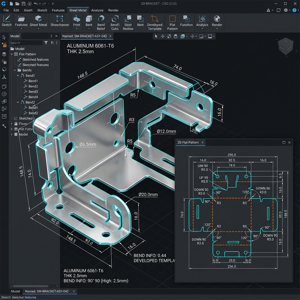
Sheet Metal Design in CAD: From Flat Pattern to Finished Component Without a Single Rework
Most sheet metal errors are not manufacturing errors. They are design errors. Ones that CAD tools can catch entirely — if the designer knows how to use them correctly.
Why sheet metal design in CAD is a discipline of its own
Sheet metal is not just a material. It is a manufacturing logic. Every fold, cut, hole, and bend in a sheet metal component follows rules that are baked into the material itself — its thickness, its grain direction, its springback behaviour. When a designer ignores these rules in the modelling phase, the shop floor pays for it.
Sheet metal design CAD tools are built to encode these manufacturing rules directly into the design environment. Features like bend allowance, K-factor, flat pattern development, and forming tool libraries exist precisely so that what you model on screen is what can actually be made. When used correctly, these tools eliminate the most expensive class of engineering errors: the ones you only discover after the first sample part comes back wrong.
The flat pattern is where design intent meets manufacturing reality
Every 3D sheet metal model has a hidden twin: the flat pattern. This is the unfolded, two-dimensional representation of the part before any bends are applied. It is what gets sent to the laser cutter or punch press. And it is where the accuracy of the entire design is tested.
Flat pattern development in CAD is not simply unfolding a 3D shape. It requires the software to calculate how much material is consumed in each bend, factoring in the K-factor — a ratio that describes where the neutral axis of the bend sits within the material thickness. A wrong K-factor means a flat pattern that, when bent, produces a finished part with incorrect dimensions.
In professional sheet metal CAD software like SolidWorks Sheet Metal or CATIA Sheet Metal Design, the K-factor can be set per material and per process, ensuring that flat patterns are accurate from the very first iteration. This is the difference between a design that goes straight to production and one that requires three rounds of sample parts before it is approved.
Bend allowance, relief cuts, and the details that separate good designs from great ones
Bend allowance in CAD is the calculated length of material needed to form a specific bend at a specific radius. It sounds like a small detail. On a simple part, it might be. On a complex enclosure with twelve bends and tight tolerances, getting bend allowance wrong by even a fraction of a millimetre can cause cascading errors that make the part unusable.
Equally important are bend relief cuts — small notches cut into the flat pattern at the end of a bend line to prevent the material from tearing or distorting during forming. CAD tools can apply these automatically, but a skilled designer knows when the automatic setting is appropriate and when a custom relief geometry is needed for a specific bend geometry or tight corner condition.
Sheet metal 3D modeling in CAD also allows designers to simulate forming operations — flanges, louvers, embosses, hems, and rolled edges — using forming tool libraries that reflect actual tooling available on the shop floor. When a design uses forming tools that match real production tooling, the drawing that leaves the engineering department is one the manufacturer can actually execute.
The most valuable sheet metal CAD designers are not those who know every software feature. They are those who understand why each feature exists — and what happens on the shop floor when it is used incorrectly.
Need a sheet metal CAD designer who knows manufacturing, not just software?
ReneChip connects you with pre-vetted sheet metal CAD engineers from India — professionals with real production experience in SolidWorks, CATIA, and more. No lengthy hiring process. Just proven talent, ready to start.
Hire from ReneChip
Connect with pre-vetted sheet metal CAD engineers from India with real production experience in SolidWorks, CATIA, and more.
renechip.com
info@renechip.com
+91 9842160709
ReneChip — 97G/4C/1, 1st Floor, PSS Jayam Towers, Teachers Colony, Tuticorin, Tamil Nadu 628008
SolidWorks vs CATIA for sheet metal — which platform fits your project?
Both SolidWorks Sheet Metal and CATIA Sheet Metal Design are industry-standard platforms, but they serve different contexts. SolidWorks is widely used in small-to-medium fabrication companies and industrial equipment manufacturers. Its sheet metal environment is intuitive, well-documented, and deeply integrated with its general solid modelling workspace. For most standard sheet metal work — enclosures, brackets, chassis, frames — SolidWorks is fast, reliable, and broadly supported.
CATIA Sheet Metal Design, on the other hand, is the platform of choice for aerospace and automotive applications where sheet metal components must be managed within large assemblies, integrated with structural analysis, and tracked across a full PLM environment. When a sheet metal part is one of thousands of components in an aircraft interior or a vehicle body structure, CATIA provides the assembly intelligence that SolidWorks does not.
What a production-ready sheet metal drawing actually contains
A completed sheet metal design in CAD does not just produce a 3D model. It produces a full manufacturing package. This includes:
- The flat pattern with all cut geometry and hole positions
- The formed view with dimensions and bend annotations
- Bend tables specifying angle, radius, and direction for each bend
- Material and finish callouts
- Tolerances that reflect what the forming process can actually achieve
Designers who understand sheet metal forming design know that tolerances on formed parts are different from machined parts. A bend location tolerance of plus or minus 0.3mm is realistic for most press brakes. Calling out plus or minus 0.05mm on a bend position is not a quality requirement — it is a drawing error that will cause the part to be rejected at inspection even when it has been made correctly.
Why remote sheet metal CAD engineers from India are delivering world-class results
India has one of the world's largest communities of trained mechanical and manufacturing engineers. Many have spent years working with global OEMs on sheet metal components for automotive, aerospace, and industrial applications before transitioning to remote design roles. This means the talent pool is not just technically trained — it is production-experienced.
When a remote sheet metal CAD engineer has worked on brake press tooling selection, flat pattern optimisation for material yield, or DFM reviews for high-volume stampings, they bring that knowledge directly into every design decision they make. The flat pattern they produce is not just geometrically correct. It is optimised for the manufacturing process it will go through.
Frequently asked questions
Your sheet metal project deserves a designer who gets it right the first time.
ReneChip gives you access to pre-vetted sheet metal CAD engineers with real production experience. No rework. No guesswork. Just engineering that works.
Get started at renechip.com
renechip.com
info@renechip.com
+91 9842160709
ReneChip — 97G/4C/1, 1st Floor, PSS Jayam Towers, Teachers Colony, Tuticorin, Tamil Nadu 628008