“Every product that carries a load, withstands pressure, or resists heat is making a structural promise. FEA simulation is how engineers verify that promise before a single prototype is built.”
Imagine a bracket on an aircraft engine mount. It looks solid enough in the CAD model. The geometry is clean, the material is specified, and the manufacturing drawing is ready. But before that bracket ever reaches a machine shop, an engineer needs to answer a question that cannot be answered by visual inspection alone: will it survive the loads it will see in service? That question is answered by Finite Element Analysis — and in 2025, it is no longer optional for any serious engineering design workflow.
FEA simulation in CAD is the process of applying mathematical analysis to a digital model to predict how it will behave under real-world physical conditions — stress, strain, heat, vibration, and pressure. This blog explains what FEA is, why it is fundamental to modern engineering, and how professional-grade simulation changes the quality of design decisions from the very first iteration.
What Is FEA Simulation in CAD — The Engineering Foundation
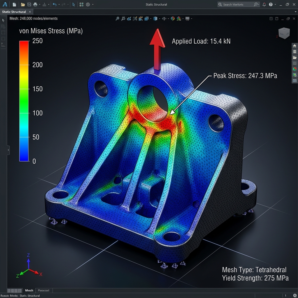
Finite Element Analysis works by dividing a complex geometry into thousands or millions of small elements — finite elements — each of which behaves according to known physical laws. By solving the equations governing each element and assembling the results across the entire model, the simulation produces a detailed map of stress, deformation, temperature distribution, or vibration mode that would be impossible to calculate analytically for complex shapes.
In a modern CAD environment, FEA is tightly integrated with the geometry model. Changes to the CAD model propagate into the simulation mesh, boundary conditions, and results — making simulation a continuous part of the design process rather than a one-time validation step at the end.
Why FEA Simulation Is No Longer Optional for Engineering Design
The traditional alternative to simulation was physical prototyping and testing — build the part, apply the load, see what happens. This approach is expensive, time-consuming, and sequential: a failed prototype sends the design back to the start of the development cycle. FEA simulation compresses this cycle radically by identifying structural weaknesses, overstressed regions, and failure modes in the digital model before any material is cut.
For industries with high safety requirements — aerospace, automotive, pressure vessels, medical devices — simulation is not just an efficiency tool. It is a regulatory and certification requirement. Designs must be analytically supported, and FEA results form part of the substantiation documentation submitted to certification bodies.
Types of FEA Simulation Every CAD Engineer Should Know
Static Structural Analysis
The most common simulation type. Applies defined static loads and constraints and calculates the resulting stress and deformation distribution. Used for brackets, frames, housings, and load-bearing components across all industries.
Modal Analysis
Calculates the natural frequencies and mode shapes of a structure — revealing which vibration frequencies will cause resonance. Critical for rotating machinery, automotive components, and any structure exposed to cyclic loading.
Thermal Analysis
Predicts temperature distribution and heat flow through a component or assembly. Particularly important for electronic enclosures, engine components, and heat exchangers where thermal gradients drive both performance and structural integrity.
Fatigue and Life Prediction
Extends static analysis to predict the number of load cycles a component can survive before crack initiation. Essential for any component subjected to repeated loading — vehicle suspension parts, aircraft structural members, and industrial machinery.
FEA Simulation in CATIA and Professional CAD Platforms
Professional-grade FEA is available within CATIA through its simulation and analysis workbenches, and through dedicated FEA platforms such as ANSYS, Abaqus, and Nastran that receive CAD geometry as input. The choice of simulation platform depends on the type of analysis, industry requirements, and the level of results fidelity required. For most industrial design applications, CAD-embedded simulation provides sufficient accuracy while minimising data exchange steps and maintaining associativity with the design geometry.
ReneChip's engineering design team applies FEA simulation as an integrated part of the 3D CAD design process — identifying structural issues at the design stage rather than at prototype testing.
Frequently Asked Questions — FEA Simulation in CAD
Q: What types of engineering problems can FEA simulation solve?
FEA simulation addresses structural stress and deformation, vibration and resonance (modal analysis), heat transfer and thermal gradients, fatigue life prediction, and fluid-structure interaction. It is applicable to virtually any mechanical component or system where physical performance must be predicted before physical testing.
Q: How accurate is FEA simulation compared to physical testing?
FEA accuracy depends on mesh quality, material model accuracy, and how well the boundary conditions represent real loading. For well-set-up simulations with validated material data, FEA results for static structural analysis typically correlate within 5 to 15 percent of physical test results. For complex nonlinear or dynamic problems, correlation requires more careful validation work.
Q: Can FEA simulation replace physical prototype testing entirely?
For most design iterations, simulation can replace physical testing significantly — reducing the number of physical prototypes required. However, for safety-critical applications in aerospace and medical devices, physical testing and simulation are both typically required for certification. Simulation does not eliminate testing; it makes testing more targeted and reduces the number of failed prototypes.
Q: Which CAD and FEA platforms does ReneChip use?
ReneChip uses CATIA and professional CAD platforms for geometry development, combined with industry-standard simulation tools for structural and thermal analysis. The specific platform depends on the client's requirements and project type. Contact info@renechip.com to discuss your simulation and analysis needs.
Q: How does FEA simulation integrate with the CAD design workflow?
In a well-integrated workflow, FEA runs directly on the CAD geometry — either within the CAD platform itself or through direct export to a simulation environment. When the design is modified, the simulation updates automatically. This associativity means simulation results are always current and design decisions are informed by real structural data at every stage.