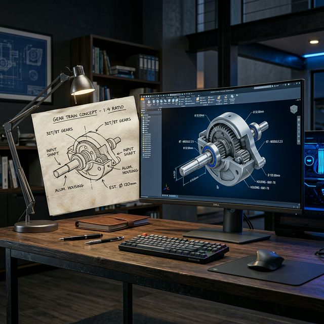
A napkin sketch has zero manufacturing value. A properly structured, toleranced, and validated 3D model is the most valuable asset in your product development process. Here is everything that happens between those two points.
There is a version of 3D modeling that is purely aesthetic — the kind used in films, games, and visualization. And then there is engineering 3D product modeling — a fundamentally different discipline where every surface, every radius, and every wall thickness carries real-world consequences in production.
Engineering 3D models are data-rich engineering documents that carry dimensional information, material specifications, surface requirements, and manufacturing constraints — all encoded in geometry that a machine can read and act upon directly.
Industry Insight: In modern Model-Based Definition (MBD) workflows, the 3D model itself is the engineering record — replacing traditional 2D drawing packages for many manufacturers. Getting the model right is no longer just important; it is the entire foundation of your product.
The 3D Product Modeling Pipeline — Step by Step
A professional 3D modeling workflow follows a disciplined sequence. Skipping stages is how projects end up in costly rework cycles:
- Concept Capture — Translating 2D sketches, reference images, or written specs into initial 3D geometry. This stage is about form exploration, not final dimensions.
- Detailed Parametric Design — Precise solid modeling with dimensions, feature relationships, and design intent captured in the model tree. Every feature must be editable and logical.
- Design for Manufacturability Review — Evaluating geometry against the intended manufacturing process. Draft angles for molding, bend radii for sheet metal, achievable tolerances for CNC.
- Assembly Modeling and Interference Check — Components in assembled context, interference detection, and fit/form/function validation in the digital environment.
- Technical Drawing Generation — Dimensioned 2D drawings, BOM, and manufacturing documentation generated from the 3D model.
- Output Preparation — Correct formats for every downstream use: STEP/IGES for exchange, STL for printing, DXF for laser cutting, or G-code-ready geometry for CNC.
Choosing the Right Modeling Approach for Your Product
Solid Modeling
Best for prismatic, machined, or injected plastic components. Solid modeling is the workhorse of mechanical design — defining enclosed volumes that map directly to CNC paths and mold cavities.
Surface (Class A) Modeling
Essential for products where external geometry needs to be aesthetically refined and aerodynamically optimized. Class A surfacing in CATIA or Alias produces the tangency-continuous curves required for automotive exteriors, consumer electronics, and premium product design.
Sheet Metal Design
Flat-pattern intelligence built into the model. Sheet metal workbenches calculate bend deductions, K-factors, and flat pattern output automatically — saving hours of manual calculation and eliminating fabrication errors entirely.
Ready to Turn Your Concept Into a Real Product?
From napkin sketch to manufacturing-ready 3D model — ReneChip's engineers handle the full pipeline with the precision your product demands.
Start a 3D Modeling Project Talk to an Engineer3D Modeling for Specific Manufacturing Processes
Every manufacturing process has geometry requirements. A model designed without process awareness will cost you dearly in tooling rework or production scrap:
- CNC Machining — Minimum corner radii matching tooling, accessible surfaces, fixturing flats, and tolerances that reflect realistic machining capabilities.
- Injection Molding — Uniform wall thickness, draft angles on all vertical faces, correct rib-to-wall ratios, gate and ejector pin placement awareness.
- 3D Printing / Additive Manufacturing — Overhang management, wall thicknesses above minimum print resolution, infill-aware structural geometry.
- Sheet Metal Fabrication — Minimum bend radii, hem specs, laser cut slot-to-tab clearances, and weld flange geometry.
- Die Casting / Forging — Parting line planning, draft, and fillet radii aligned with die machining and ejection physics.
Your Product Deserves Engineering That Matches Its Ambition
Get a free 30-minute engineering consultation on your 3D modeling project with ReneChip's senior design team.
Book Free Consultation Download Brochure